Coordinate Extractor
User guide
Coordinate Extractor working object
Coordinate Extractor uses a Positioning block, hereafter called a Point, with ID, CODE, STATION and TYPE attributes.
Attribute definitions:
ID- Point number (a unique number is recommended).
CODE- Code assigned to the Point (may be blank).
STATION- Point position along a linear object, measured as a distance from an arbitrary zero; i.e. station or chainage (may be blank).
TYPE- Point type, assigned according to the selected option:
1– on a boundary (Boundary);2– on the axis of a linear object (Axis);3– isolated Point (Center).
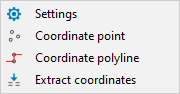
1. Coordinate point
Create individual Points by picking their locations in the drawing.
Prompts:
Enter point starting number (1, A1, 1A, A, A1B) <1>:- Enter the first Point number. Subsequent Point numbers are incremented automatically.
Select point type [Axis/Boundary/Center] <Center>:- Select the Point type: axis, boundary or isolated Point.
Enter point code:- Enter the Point code, if required.
Pick point location:- Pick the Point location. The prompt repeats until the command is cancelled.
Note. Point type and code are specified once per command run.
2. Coordinate polyline
Create Points at polyline vertices and/or at positions along polylines.
First prompt:
Select positioning mode [Vertex/Measure/measure With vertex] <Vertex>:- Select where to place Points:
Vertex– at polyline vertices only;Measure– at the specified interval along polylines only;measure With vertex– at the specified interval and at polyline vertices.
2.1 After selecting Vertex
Select point type [Axis/Boundary/Center] <Boundary>:- Select the Point type: axis, boundary or isolated Point.
Boundary sets TYPE to 1; Center sets it to 3. Axis sets TYPE to 2 and assigns stationing to STATION.
After selecting Boundary or Center
Enter point starting ID (1, A1, 1A, A, A1B) <1>:- Enter the first Point number. Subsequent Point numbers are incremented automatically.
Enter point code:- Enter the Point code, if required.
Select polylines:- Select the polylines whose vertex coordinates are required.
After selecting Axis
Enter point station beginning value <0.0000>:- Enter the starting station or chainage of the linear object.
Select ID numbering mode [Station/Normal] <Station>:- Select the Point ID numbering mode:
Station–IDreceives stationing values;Normal–IDreceives sequential numbers.
After selecting Station
Enter ID prefix for stationing (A, B, ...) <>:- Enter a stationing prefix, if required.
Enter point code:- Enter the Point code, if required.
Select polylines:- Select the polylines on which to create Points.
After selecting Normal
Enter point starting ID (1, A1, 1A, A, A1B) <1>:- Enter the first Point number. Subsequent Point numbers are incremented automatically.
Enter point code:- Enter the Point code, if required.
Select polylines:- Select the polylines on which to create Points.
2.2 After selecting Measure
First, specify the Point spacing:
Segment length <100.0000>:- Enter the interval between Points along the polylines.
Next, select the Point type (Axis, Boundary or Center). The subsequent numbering, code and polyline-selection prompts are the same as for Vertex.
The starting station and Station/Normal numbering mode are requested only when Axis is selected.
2.3 After selecting measure With vertex
The prompts are the same as for Measure. In addition to Points placed at the specified interval, Points are created at polyline vertices.
3. Extract coordinates
Export the selected Points' coordinates to a file and/or display their coordinate list in the drawing as a Table object.
Prompts:
Select positioning block references (enter _ALL for all):- Select the positioning blocks. Enter
_ALLto select all blocks that match the selection criteria. Digits after the decimal point <2>:- Enter the number of decimal places.
Type of file [Gsi16/Txt]:- Select the file format, then choose a file name and location in the save dialog. If no file is needed, press Enter to skip this prompt.
Pick table location:- Pick the insertion point for the coordinate-list table. If no table is needed, press Enter.
Number of rows in the table:- Enter the number of data rows in the table. The default is the number of selected Points. This prompt appears when creating a table.
Note. You can save a file, create a table, or produce both outputs.
When working through a layout viewport, the program switches to paper space before prompting for the table location. The table is created there at the specified insertion point. On the Model tab, the table is created in model space. Both the table and the file contain the model Points' coordinates.
4. Settings
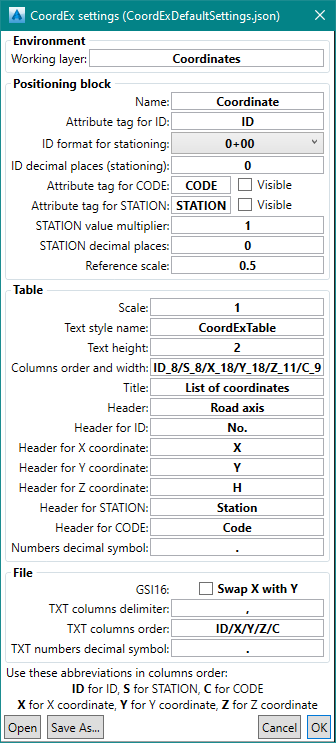
The Settings command configures:
Environment– the working layer;Positioning block– the working object (Point);Table– the appearance of the coordinate-list table in the drawing;File– the export file format.
Program settings can be saved to a configuration file. Multiple configurations can be saved and used.
Note. When preparing stake-out reports, we recommend working in paper space.